The machine, in a browser tab.
Like remote desktop, except it does not run on the machine. A small board plugs into that machine’s HDMI and a USB port and hands you its screen, keyboard and mouse in a browser — so it still works when the machine is stuck in the BIOS, or has no operating system at all. That is an IP-KVM, and this one is built from an ESP32-P4 and a TC358743 HDMI bridge.
New to this? What an IP-KVM is, and why you might want one →


A commercial KVM-over-IP does this too, for a great deal more money. This one captures HDMI, presents itself over USB as a keyboard and mouse, hands the target a disk image to boot from, and serves the whole thing over HTTPS from a megabyte of firmware — the console inside it is 44 KB.
What it does
What the firmware ships with. Anything the hardware cannot support, the device shows disabled with the reason — it does not pretend.
Any device you have to hand
Laptop, phone or tablet. Nothing to install on either end, and touch gets a trackpad and a keyboard of its own.
Follows the target
800×600 firmware screen to 1080p desktop, followed without being told.
Clicks land where aimed
An absolute pointer: the target’s mouse acceleration cannot drift the cursor off the button you meant.
Copy text off a BIOS screen
A BIOS, a boot loader, a console: select it with the mouse like a page, or copy the whole screen. Not OCR — the characters are read from the grid the firmware drew them on, so a serial number comes back exactly or not at all.
MJPEG or H.264
Both encoded by hardware. H.264 costs a fraction of the bandwidth on a screen that barely changes.
Boot from a disk image
A rescue or live image, handed to the target as a USB drive it can boot from — from a microSD card, or a small one kept in the device’s own flash with no card at all.
Updates itself
Two app slots and automatic rollback: an image that fails to start returns the device to the one that worked. The console shows the version on each slot, and can boot the other one on demand.
HTTPS and a login
A certificate the device issues itself on first boot, and a password you can clear with the board button if you forget it.
Lives in Home Assistant
Turn on MQTT and it arrives as one auto-discovered device, sensors and buttons included.
Reach it over WireGuard or Tailscale
Reach it across the internet without exposing it. WireGuard for a classic hub, or Tailscale to join a tailnet with no gateway, VPS or port-forward. Off by default.
WiFi, with a rescue hotspot
Join a network or be the access point, on boards with an ESP32-C6. Out of range, a rescue hotspot and a captive portal put the console on your phone.
A little status screen
A cheap OLED or a round colour LCD shows the IP, link, capture and health with no browser open. Pins are picked in the console.
The round one also fills with a code your phone scans to join the rescue hotspot, and draws the recovery button press as a ring.
Wake a machine that went to sleep
A key press wakes it, the way a real keyboard would. Failing that, Wake-on-LAN or the power button.
Power and reset, held down for you
Two optocouplers on the front-panel header put the machine’s own buttons in the browser. It reads the power LED back, so the state shown is the machine’s.
Watches the screen while you do not
Give it phrases — no boot device, kernel
panic — and it alerts with a still attached. A screen
gone one flat colour counts too. It can push the alert, with a
screenshot, to Telegram or a webhook.
Records to its own card
A button writes the screen to the microSD card as H.264, and a dashcam keeps the last minutes and saves them when a stop screen shows or the power drops — as an MP4 with chapters, and to Telegram if you want. Keystrokes go in as subtitles, and it all plays back in the console.
Runbooks: a macro that can wait
wait Press F2, key f2, wait Boot.
Run on the device, so the tab can close; a button each in Home
Assistant, or on a schedule. The language.

What arrives in Home Assistant
One device, discovered automatically over MQTT. Off by default, TLS optional.
- Sensors — frame rate, HDMI signal, resolution, codec, bitrate, viewers, chip temperature.
- The target — its power state, whether it sees the keyboard, and whether its USB port has power at all.
- Buttons — power, a hard off, reset, Wake-on-LAN, restart the KVM.
- A camera — a still of the target’s screen, on demand or when the screen watch finds a phrase.
- The jiggler — a switch, with its interval beside it.
- An update entity — the version running, the version published, and the button that installs it.
- Diagnostics — free memory and the largest block in it, skipped frames, which firmware slot is running and why the device last booted.
Virtual media, honestly. Images live on a microSD card, formatted FAT32, up to 4 GB each, and the console uploads them. How fast the card runs depends on the board, and the device finds that out per card. On the Function EV and the P4-ETH the card runs at 40 MHz: it reads at about 8.5 MB/s, and an upload over Ethernet is about 3.5 MB/s on the Function EV and 1.5 MB/s on the older P4-ETH chip. Pause the video while you upload: the encoder and the Ethernet chip share a bus, and the upload is several times faster without it. The other boards with a slot are wired the same way and start at 40 MHz too; they have not been run on hardware yet. For the rescue case there is another option that sidesteps the card entirely: a small image (iPXE, memtest, a DOS floppy) kept in a 4 MB flash partition, served from memory and writable from the browser.
FAQ
How is this different from IPMI?
IPMI, the BMC chip built into server motherboards, manages a machine from the inside: real power control, internal sensors, POST codes, over a standard protocol. But it lives only on server-class hardware, and the full remote console is often behind a license.
ESP-KVM is external. It clips onto any machine with an HDMI output and a USB port, captures the physical video, and acts as its keyboard and mouse — bringing the remote console, virtual media and wake-on-LAN part of what a BMC does to hardware that has no BMC and never will: a desktop, a laptop, a mini-PC, an SBC, for about $40. It can press the machine’s power and reset buttons and read its power LED through optocouplers (ATX power control), though it does not read the host’s internal sensors the way a BMC does. Think of it as closer to PiKVM than to IPMI: not a replacement for a BMC on a server, but the useful slice of one for everything that never had a BMC.
What USB cable connects the device to the target (Waveshare ESP32-P4-ETH)?
ESP-KVM presents the keyboard and mouse to the target over the ESP32-P4’s high-speed USB OTG (OTG_HS). It has to be a proper USB data cable, not a charge-only one — the data lines are what carry the keyboard and mouse.
On the Waveshare ESP32-P4-ETH specifically, OTG_HS is not on a USB port at all — it is brought out on a small MX1.25 header (the board’s single USB-C is the CH343 flashing/console port). So you need an MX1.25-to-USB cable ending in a male Type-A plug — ESP-KVM is the USB device, so it plugs into the target’s USB port. A link to one that fits is in this discussion.
On other ESP32-P4 boards the OTG_HS may be routed to a USB-C port instead — check your board’s pinout.
The mouse pointer lands in the wrong place on the target — why?
Almost always because the target has more than one display. ESP-KVM presents itself as an absolute pointing device by default, the way a graphics tablet does: it sends “the pointer is at this position” rather than “move this far”. That is what lets the cursor land exactly where you aim it, with nothing to capture and nothing to run away.
The catch is that an absolute device addresses the target’s whole desktop, not the one output you are watching. With a second monitor attached, that desktop is wider than the screen ESP-KVM captures, so your side of the picture is stretched across both. With two equally wide screens the pointer travels twice as far as the mouse, and half of the picture aims at the display you cannot see — move into it and the cursor simply disappears onto the other monitor.
Two ways out. Unplug or disable the target’s second display while you are working through ESP-KVM — then the desktop and the captured screen are the same thing again. Or switch Settings → Input → mouse mode to relative, which sends movement instead of position and so does not depend on the desktop’s size or layout; click the picture to take control, and use Relative sensitivity if the speed does not suit you.
A pointer that drifts only near the edges while it is accurate in the middle is a different thing entirely, and one that affected macOS targets — that one is fixed.
Can I use a different ESP32 chip (S3, S31, …) instead of the P4?
No — this design needs two things that, across Espressif’s line-up, only the ESP32-P4 has together: a MIPI-CSI-2 receiver and a hardware H.264 encoder.
The capture board (a Toshiba TC358743) outputs MIPI-CSI-2, so the host chip needs a CSI-2 receiver to read it. The other ESP32 parts — including the newer ESP32-S31 — have a DVP (parallel) camera interface, not CSI-2, so they can’t take the bridge at all. And moving 1080p leans on the P4’s hardware H.264 encoder; the S-series has a JPEG codec but no H.264, so software encoding on the cores wouldn’t keep up.
The S31 does have things the P4 lacks (WiFi 6 on-die, no co-processor), so if Espressif ever ships a P-series successor with the radio built in, that would be the dream chip for this — but for now the P4 is the one with the CSI-2 + H.264 combination it needs.
Which ESP32-P4 boards do not work?
Being an ESP32-P4 board is not enough. Five things decide it, and a board that misses any one of them cannot run ESP-KVM as it is:
- 32 MB of PSRAM. The frame buffers are allocated once, for the largest mode the bridge can deliver: 12.5 MB at 1080p on rev 3.x silicon (three buffers of 1920×1088 YUV422), 11.9 MB on rev < 3.0 (two of 1920×1080 RGB888) — before the H.264 encoder asks for its reference frame. An 8 MB part cannot hold even the first of those, and video shuts itself off with an explanation.
- 16 MB of flash. Two OTA slots and the rescue image do not fit in 4 or 8 MB.
- A camera connector the bridge can reach. Two CSI-2 data lanes, and 3.3 V and I2C on the same connector or somewhere you can wire them from. Some boards bring only 1.8 / 2.8 V sensor rails to the FPC and level-shift the I2C down with it — then a ribbon alone is not enough.
- USB OTG-HS on something you can plug into the target. A USB port or a header. A board that only exposes D+/D− on an edge connector needs a carrier board first.
- A way onto the network — an Ethernet PHY on the board, or an onboard ESP32-C6.
A worked example: the LILYGO T-Halow P4 is an ESP32-P4 with a camera FPC, an ESP32-C6 and Wi-Fi HaLow, and it fails on four of the five. It has 8 MB of PSRAM; its Ethernet RMII and its USB OTG D+/D− are brought out only on the M.2 edge connector, so there is no PHY and nothing to plug the target into; and its 24-pin camera FPC carries no 3.3 V and a 1.8 V I2C. The C6 is wired exactly as on the Function EV board and would work — but the rest is a carrier board and a custom ribbon away, and the PSRAM still rules out 1080p.
One thing worth checking with the schematic rather than a product photo: which camera connector. The 15-pin, 1.0 mm one is the Raspberry Pi camera connector, and the ribbon that comes with a C790 plugs into it as it is. The 22-pin, 0.5 mm one carries the same signals but needs an adapter ribbon. And on either, 3.3 V and a 3.3 V I2C have to be on the connector.
About a dozen ESP32-P4 boards have been read through this list, the ones that fail included — mostly on USB, not on memory. They are written up in docs/PORTING.md. If yours is not there, open an issue with a link to its schematic.
Wi-Fi HaLow, for what it is worth, is not a way around any of that: the modules on those boards use a vendor driver ESP-IDF does not carry, and 802.11ah’s narrow channels cannot hold a video stream anyway.
Measured, not estimated
Every number here came off the hardware, at 1080p. The ones that contradicted the documentation are written down in the hardware notes.
| MJPEG | H.264 | |
|---|---|---|
| Frame rate — Waveshare ESP32-P4-ETH (rev v1.3) | 20 fps | ~7 fps |
| Frame rate — Function EV (rev v3.2) | 23 fps | 22–24 fps |
| Idle screen | 0 kbit/s | 170 kbit/s |
| Screen in motion | 8.5 Mbit/s | ~500 kbit/s |
| Chip temperature, full load — rev v1.3 | 46 °C in open air | |
| Chip temperature, full load — rev v3.2 | 34 °C in open air | |
H.264 costs a fraction of MJPEG’s bandwidth either way — an idle screen is 170 kbit/s against MJPEG’s 8.5 Mbit/s in motion — and browsers decode it through WebCodecs, which they only offer on secure pages (one reason the device serves HTTPS). What differs between the two boards is the frame rate.
The revision-3.x win we predicted actually landed
The Waveshare figures come from an ESP32-P4 revision v1.3, and the biggest cost in its H.264 path is something that revision forces on us. Below silicon revision 3.0 the CSI receiver cannot hand over YUV420 and the encoder will not accept RGB, so every frame takes a detour through the pixel accelerator to change colour space — measured at ~104 ms of the ~150 ms a 1080p frame costs.
On the Espressif Function EV board (revision v3.2) that detour is gone: the capture feeds YUV422 straight into the encoder, no conversion pass. H.264 goes from ~7 fps to 22–24 fps at 1080p (and 28 fps at 720p) — as fast as MJPEG (23 fps) but at a fraction of the bandwidth — and the chip runs cooler doing it, 34 °C against 46 °C. The revision test was in Espressif’s own driver, quoted in the hardware notes; the prediction held.
Where it stands
An honest status board, the same one the device reports about itself.
| Video capture, resolution changes, MJPEG, H.264 | works |
| Keyboard, absolute and relative pointer, media keys, paste | works |
| Touch mode for phones and tablets (trackpad, on-screen keyboard) | works |
| Multiple viewers, one in control at a time with takeover | works |
| HTTPS, login, physical password reset | works |
| Bring your own TLS certificate (or the self-signed default) | works |
| Firmware updates over the network, with rollback | works |
| Thermal protection | works |
| Recording the screen and screenshots to the device’s microSD card | works |
| A dashcam — the last minutes saved when a stop screen shows, a phrase appears or the power drops | works |
| Timelapse, keystroke subtitles, playback and text search in the console | works |
| Virtual media — boot the target from a disk image | works (card or on-flash) |
| Guessing the target’s OS from how it enumerates USB | works |
| User macros — replayable key sequences | works — the language |
| Runbooks — a macro that waits for words on the screen, run on the device | works; text screens only |
| Wake-on-LAN (no ATX wiring) | works |
| Static IP addressing, or DHCP | works |
| Status screen on the device (OLED or round LCD), either way up, with a scannable hotspot code | works |
| IPv6 alongside IPv4, autoconfigured | works |
| WiFi — station or access point, with a rescue hotspot and captive portal (boards with an ESP32-C6) | works |
| ATX power control (power/reset buttons, power-LED sensing) | works |
| Home Assistant over MQTT (auto-discovered sensors and buttons) | works |
| VPN — WireGuard or native Tailscale (pick one; Tailscale needs no gateway or port-forward) | works |
| HDMI audio | not yet |
Not for the public internet. There is a login and there is TLS, but nothing here has been through a security review, and a device holding a keyboard on someone else’s machine is worth more to an attacker than most things on a network. Keep it on a network you trust, or reach it over the built-in WireGuard client or native Tailscale.
What you need
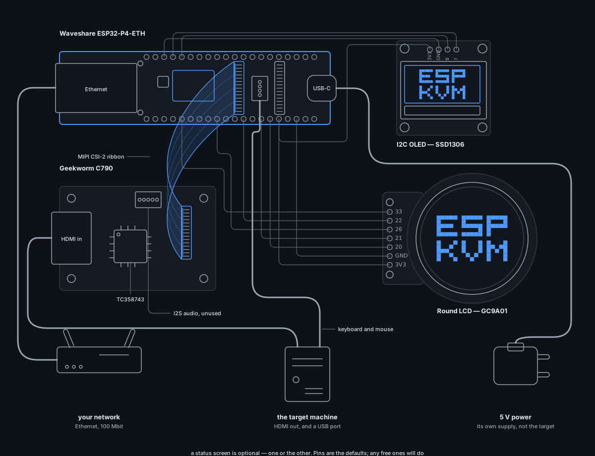
Two boards and three cables, plus optional modules — power control and a little status display. Everything is off-the-shelf; any equivalent works, these are the ones this project is built and tested on.
Boards that have been run on hardware
Six of these have had this firmware on them, on someone's bench. Any of them does the whole job.

Waveshare ESP32-P4-ETH
ESP32-P4 with 100M Ethernet, a Raspberry-Pi-compatible CSI connector, USB-C OTG and a microSD slot. Another ESP32-P4 board with Ethernet and the same CSI connector can run it too — the pins are set in menuconfig, not the code.
Waveshare product page →
Espressif ESP32-P4 Function EV Board
Espressif’s own ESP32-P4 board, with a rev 3.2 chip. It has its own build target and the browser flasher offers it directly. The newer silicon captures native YUV422 straight into the video encoders, which frees the colour-convert engine and lifts 1080p to a little over 20 fps.
Espressif user guide →
Waveshare ESP32-P4-NANO
Same IP101 Ethernet and onboard ESP32-C6 as the boards above, with 32 MB PSRAM and 16 MB flash. Contributors confirmed capture, USB and Ethernet on both silicon revisions, and WiFi on rev 3.1. The USB lead to the target is an A-to-A cable with the 5 V wire cut.
Waveshare product page →
Guition ESP32-P4-M3-Dev
A display board (4.3″ MIPI-DSI touch, unused by the KVM) that also carries Ethernet and an ESP32-C6; 32 MB PSRAM, 16 MB flash. Two USB-C ports — the target goes on the OTG-HS one. A contributor confirmed capture, USB and Ethernet (on pre-3.0 silicon).

Waveshare ESP32-P4-WIFI6
The PoE board without the wired port, contributed by someone who has one: capture and the USB keyboard and mouse are confirmed on hardware. 32 MB PSRAM, 32 MB flash. Its WiFi link used to stall; since 0.41.1 the chip's own pull-ups are switched on for this board and it holds. That is one board and one tester, and WiFi is the only way in here, so tell us if yours behaves differently.
Waveshare product page →
Waveshare ESP32-P4-WIFI6-POE-ETH
The first supported board that takes PoE: one cable
to a KVM in a rack instead of two. Same Ethernet, microSD and
ESP32-C6 wiring as the boards above; 32 MB PSRAM, 32 MB
flash, and a full-size USB-A port for the target. Confirmed by a user
on rev 3.x silicon with the p4-poe-rev3 image:
1080p over H.264 at 23 fps. Check the chip revision in the boot
log before flashing — the older image has not been run on it yet.

M5Stack Unit PoE-P4
A matchbox that takes power, network and video on two cables: 32 MB PSRAM, 16 MB flash, 100M Ethernet and 802.3at PoE. The odd one out here — its capture is not a C790 on a camera ribbon but M5Stack’s own Add-on Display In, below, which plugs onto a 24-pin flat cable and brings a microSD slot with it. 23 fps at 1280×720, checked on hardware. The rev 3.x PoE-P4X takes the same firmware from an image of its own, and pays neither of the older chip’s costs.
M5Stack documentation →Boards built from a schematic, never run
Their pins were read off the vendor's schematic, the images build and are published, and that is the whole claim. Flashing one cannot damage it - the worst case is an image that does not start, and a reflash undoes that. Tell me how it goes and the board moves up a block.

Waveshare ESP32-P4-WIFI6-DEV-KIT
Ethernet and WiFi 6 on one board: a 100M magjack that also takes PoE, plus the ESP32-C6. Same pins as the boards above, so the build is almost the stock one; 32 MB PSRAM, 32 MB flash. Its USB OTG port is switched between host and device by a jumper — the KVM needs device. Built from the schematic, not yet run on one.
Waveshare product page →
Waveshare ESP32-P4-Module-DEV-KIT
The board above, packed into a module: the P4, the ESP32-C6 and 16 MB of flash under one shield, 32 MB PSRAM, on a carrier with 100M Ethernet, a card slot, a 2x20 header and four USB-A sockets. Every pin the KVM touches is one already in use, and the CSI connector is the 15-pin Raspberry Pi one, so a C790 ribbon plugs straight in. A jumper picks whether the OTG-HS goes to a Type-A socket or an internal hub — the KVM wants the socket. Built from the schematic, not yet run on one.
Waveshare product page →
Waveshare ESP32-P4-NANO-WIFI6-DB
The NANO with a dual-band ESP32-C5 in place of the C6, so it can join a 5 GHz network — the first supported board that can. 32 MB PSRAM, 16 MB flash, 100M Ethernet with a PoE header, a Type-A port for the target, and the 15-pin Raspberry Pi camera connector, so a C790 ribbon fits. It carries rev 3.x silicon, so it has one image and no pre-3.0 twin.
Waveshare product page →
DFRobot FireBeetle 2 ESP32-P4
60 x 25 mm, and everything the KVM needs on it: 32 MB PSRAM, 16 MB flash, an ESP32-C6 for WiFi 6 and the 15-pin Raspberry Pi camera connector, so a C790 ribbon plugs straight in. No wired port — WiFi is the only link. Two USB-C sockets, and they are not interchangeable: one is power, flashing and the log, the other is the OTG-HS that goes to the target. Built from the schematic, not yet run on one.
DFRobot product page →
VIEWE ESP32-P4-Pi
A Raspberry-Pi-shaped carrier for VIEWE's own P4 module: 32 MB PSRAM, 16 MB flash, an ESP32-C6, 100M Ethernet, microSD and the 15-pin Raspberry Pi camera connector, so a C790 ribbon fits. Three USB ports — one Type-C for power, flashing and the log, the other Type-C is the OTG-HS that goes to the target, and the Type-A socket is a host port the KVM does not use. Both schematics are published, carrier and module, so every pin was read rather than guessed.
VIEWE documentation →
Not the board you have?
Open an issue with a link to its schematic. If it clears the five points above, adding it is a config overlay and a build — the pins live in menuconfig, not in the code — and it can be in the next release. That is how most of the boards on this page arrived. If it does not clear them, the answer says which point it fails on, which is worth having before the board is.
Ask for a board →The capture board
This is what turns the target's HDMI into something the ESP32-P4 can read. Two are confirmed on the TC358743 bridge and work with any board on this page: the C790 this project is built on, and Waveshare's adapter. A third, M5Stack's Add-on Display In, carries a Lontium LT6911D instead and is now driven too - but it plugs onto M5Stack's own PoE-P4 units and onto nothing else.

Geekworm C790
A TC358743 HDMI → MIPI CSI-2 bridge that turns the target’s HDMI into a camera stream the ESP32-P4 can read. Any other TC358743 capture board should do just as well — the firmware talks to that chip, not to the board around it. The C792 is the same bridge with a splitter in front and should work too, though nobody here has run one; use its 15-pin connector, and see the README on what its EDID may do to a 1080p60 source.
Geekworm wiki page →
Waveshare HDMI to CSI Adapter
The same TC358743 bridge on Waveshare’s board (product 19137), so the firmware treats it exactly like the C790. A full-size HDMI input, and a 15-pin Raspberry Pi camera connector that also powers it. A user confirmed it on the ESP32-P4-WIFI6-POE-ETH: 1080p over H.264 at 23 fps.
Waveshare wiki page →
M5Stack Add-on Display In
Not a TC358743: a Lontium LT6911D, and a microSD slot with it. It plugs onto the 24-pin flat cable on M5Stack’s Unit PoE-P4 and PoE-P4X — that is the ribbon in the picture, not the 15-pin Raspberry Pi camera cable every other board here uses, so it fits none of them and none of them drives it. Together they are the smallest complete KVM of the lot: 23 fps at 1280×720 over MJPEG, H.264 as well, power, network and video on two cables.
M5Stack shop page →Power control (optional)
Two wires to the machine's front-panel header let the console press its power and reset buttons. A relay module does the same job - the firmware only pulses a pin, and which way round it triggers is a setting. Reading the power LED back is the one part a relay cannot do: that input wants an optocoupler.

PC817 optocoupler module
A pair of these cheap two-channel boards lets ESP-KVM press the target’s power and reset buttons and read its power LED, electrically isolated from the machine. A relay board does the two buttons just as well, but cannot sense the LED. Skip it all and everything else still works. Wiring is in docs/wiring.md.
Status display (optional)
A small screen on the box, so you can see its address and link without opening a browser.

I2C OLED — SSD1306 / SH1106
A mono OLED on four wires, in any of its usual sizes from 0.96″ 128×64 down to 0.49″ 64×32. It shares the capture chip’s I2C bus, so it needs no pins of its own — the device draws its IP, link, capture status and health across a few pages, fewer of them on shorter glass. Mount it either way up; the picture turns over in the settings.

Round LCD — GC9A01
A 1.28″ 240×240 round colour SPI LCD, e.g. the Waveshare module. Wire its SPI pins to any free GPIOs and choose them in the console; the same status pages, in colour — plus the hotspot join code and the recovery-button ring, which need the room.
A case (optional)
Printed by people who built one. All three models are published.

ESP32-P4-ETH KVM Case
A printed box for the ESP32-P4-ETH and the C790 together, published by Colin Hickey. It keeps the two boards and the OTG cable to the target tidy; HDMI, Ethernet and that cable all come out of one side. The P4 board is held tightly, so take care when you take it out again. Photo by the author, CC BY-NC.
Model on Printables →
KVM case for ESP32-P4-ETH and C790
A second box for the same pair of boards, adapted for this project by Fabrion365 after a user asked. Vented along one side, with the ports coming out of the ends. Photo by the author.
Model on MakerWorld →
ESP32-P4-NANO / C6 KVM case
A compact box for the ESP32-P4-NANO with its ESP32-C6 and the C790, by Crisspii. Ethernet, USB and HDMI come out of one end, the sides are vented, and there is room for a small heatsink. Five M2 screws close it. A version with a display is planned. Photo by the author.
Model on MakerWorld →Built on someone else’s work
This project exists because of Jonathan Rowny and
his p4kvm proof of
concept. He was the one who got an ESP32-P4 to pull frames off a
TC358743 at all, and put it in the open with a working
demonstration for anyone
to build on — this is that thing built on. Two pieces of his
work are reverse engineering no datasheet would have handed us: the
TC358743 bring-up sequence, and the direct programming of the
ESP32-P4’s MIPI_CSI_BRIDGE registers, which the
camera API does not expose. Both still carry this firmware; the
layers above them were rewritten. Thank you, Jonathan, for
publishing it.
In the press
Independent coverage of ESP-KVM:
- Hackaday — “A Capable KVM Built With The ESP32”
- CNX Software — “ESP-KVM – An open-source IP KVM solution based on ESP32-P4 RISC-V MCU”
- RISC-V International — “This Week in RISC-V” (July 31, 2026)
- Circuit Rocks — “ESP-KVM Turns an ESP32-P4 Into a $45 Open-Source IP KVM”
- LAB1612 — “ESP-KVM: un IP-KVM open source con un solo ESP32-P4, alternativa economica a PiKVM e JetKVM” (in Italian)
- SMZDM — “一周两条GBA满帧视频、一块59元新板:ESP32-P4终于“能玩了”,但上手前先看这三个问题” (in Chinese)
- Open Source For You — “Microcontroller Enables Remote Device Access”
- Solid State Bytes — “A Raspberry Pi That Boots Straight Into AI, an ESP32-P4 KVM, and More”
- LearningBot — “Build of the Week”
- EdigE — “An ESP32-P4 turned into a real IP-KVM with HDMI, H.264, USB HID and boot images” (in Russian)
- Wels — “5 Minutos de Miercoles #22”, from 5:42 (on video, in Spanish)
- 私人定制 Blog — “GitHub 开源 ESP-KVM:$45 把 ESP32-P4 变成 IP 远程控制卡——HDMI 采集 + 浏览器键鼠 + 虚拟光驱,替代 $300 商业方案” (in Chinese)
- log8.kr — “ESP32 IP-KVM 홈랩 원격 복구 설계”, a recovery-and-security checklist built around the device (in Korean)
- BearBlogtech — “ESPKVM an Open Source Kvm with IP and an ESp32”, a build log written after the author’s $800 datacentre KVM died
Also picked up and translated internationally — French, Greek, Spanish, Russian, Chinese, Japanese, Thai and German.
It has started turning up as a reference point when other devices in the category are written about, rather than only as a story of its own — PC de Mano names it alongside the Sipeed NanoKVM in a review of the USBridge-KVM 2.0 (in Spanish).
Waveshare, the maker of the capture adapter, links ESP-KVM from its HDMI to CSI adapter wiki.
Writing about it? There is a page with everything you would otherwise have to ask me for: descriptions of three lengths to paste, the whole feature list, the facts, the limits I would rather you printed than guessed, photographs, the two clips and the logo — ESP-KVM for writers.
Support and community
ESP-KVM is free and open source. If it saved you a trip to a dead machine you can buy me a coffee — entirely optional. And if you would rather help build it, issues, ideas and pull requests are just as welcome.

Release notes, work in progress and the occasional picture of a board go out on Telegram and X, and the clips live on YouTube:
Ask a question Report a bug Contribute on GitHub
One person builds this, with no budget for ads, so most people who could use it never hear of it. If it was useful to you, telling somebody helps more than anything else:
Built with the help of these contributors: